

ISO Certified ISO Certified
Trusted Partner Trusted Partner

Startup India Certified Startup India Certified
INDUSTRIAL ETHERNET CONTROL

8 Channel
Ethernet Relay Board

Nex-G Automation's 8 channel ethernet relay board is intended for distributed equipment groups and medium-sized automation panels. It combines TCP/IP-based remote switching with eight independently controlled outputs for compatible industrial control applications.
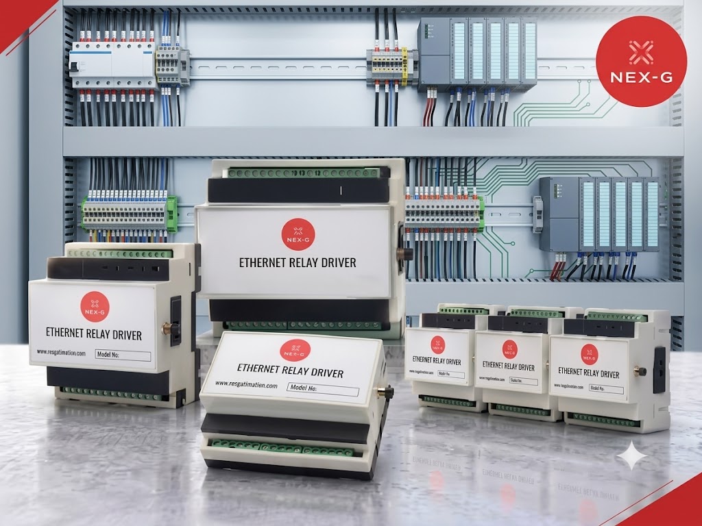
8 Channels TCP/IP Client Mode DIN Rail Mount Up to 10A
Integration Guide
Nex-G Automation Ethernet relay range reference image
Nex-G Automation LLP | Range reference image
TCP/IP Ethernet Communication
8 Relay Configuration
10A Maximum Relay Rating
12/24V DC Supply Options

8 Channel network relay control for distributed equipment groups and medium-sized automation panels.

The 8 channel ethernet relay board provides eight independently controlled outputs through a compatible Ethernet control application. It is intended for distributed equipment groups and medium-sized automation panels. Client Mode communication allows the controller to connect to a configured server and receive supported switching commands.
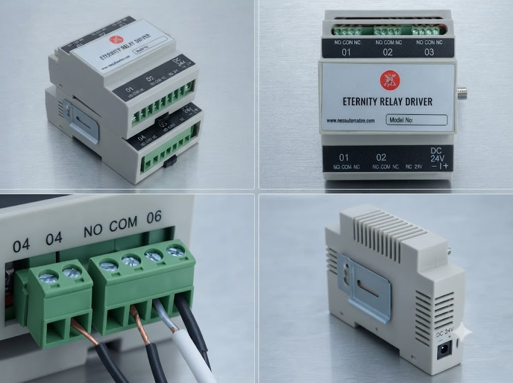
Ethernet TCP/IP communication 8 independently controlled relay channels Client Mode operation Up to 10A relay rating 12V / 24V DC options DIN rail / wall mounting options
Nex-G Automation TCP/IP network relay controller

From IP commands to physical relay switching.

The Ethernet-based output controller connects to a network and uses configured IP communication to receive switching instructions. The selected relay channel can then operate the connected electrical circuit according to the application requirements and relay contact ratings.

01Ethernet Link
02Client Mode
03IP Command
04Channel Switching
05Keep-Alive
06Remote Control

How the Ethernet relay controller works.

The network relay board connects through Ethernet, operates in its configured client mode, receives IP-based control instructions and changes the state of the selected physical relay channels.

01 Network Connection The relay board connects to the Ethernet network using TCP/IP communication.
02 Client Mode The device uses its configured client-mode settings to connect to the target server address.
03 IP Command The connected control application sends the required command according to the device communication interface.
04 Channel Switching The selected relay channel changes state to control the connected electrical load.
05 Connection Monitoring Keep-alive heartbeat packets can help monitor the network connection status.

From network instruction to relay operation.

The TCP/IP relay module converts configured network commands into physical relay state changes for connected electrical equipment.

01
Server Connection
The relay operates as a client node and connects to the configured server.
→
02
Command Received
The network module receives the required IP-based control instruction.
→
03
Relay Switching
The selected relay channel changes state to control its connected load.
→
04
Connection Monitoring
Configured heartbeat packets help monitor network communication.

Flexible control for connected electrical equipment.

01 · Direct IP Control Control relay channels from compatible upstream server or control applications using the supported TCP/IP command interface.
02 · 8 Channel Output Control Plan switching for distributed equipment groups and medium-sized automation panels using eight independently controlled outputs.
03 · Client Mode Operation Configure the network relay controller to connect to the specified target server address.
04 · Keep-Alive Monitoring Use configured heartbeat communication to help check the network connection status.

Key capabilities

Designed for network-based output control, flexible relay configurations and integration into suitable industrial control environments.

01
TCP/IP-Based Relay Control
Control the relay module through its supported Ethernet communication interface and configured IP command system.
02
8 Channel Configuration
This configuration is intended for distributed equipment groups and medium-sized automation panels, with eight independently controlled outputs.
03
Client Mode Operation
Configure the network node to establish communication with the specified target server address.
04
Remote Equipment Switching
Use network-based commands to operate connected equipment without requiring a person to switch each relay locally.
05
Industrial Mounting Options
DIN rail and wall-mount form-factor options support installation in suitable industrial control panels and enclosures.

Core System Advantages

Remote Network Access Operate connected relay channels through a compatible network control application.
Flexible System Integration Use the supported communication interface to connect with suitable PC-based and industrial control environments.
Scalable Relay Deployment Match the output requirements of distributed equipment groups and medium-sized automation panels to eight independently controlled outputs.
Electrical Switching Capacity Relay contact ratings support loads within the specified voltage and current limits.

8 Channel Ethernet Relay Board Specifications

Industrial Ethernet Relay Controller
Communication Interface Ethernet (TCP/IP) Network communication
Operating Mode Client Device Configuration Network client operation
Relay Channels 8 Channels Individual output control
Relay Contact Type SPDT / SPST Model dependent
Relay Rating Up to 250V AC / 30V DC Up to 10A maximum, subject to contact and load conditions
Power Supply 12V / 24V DC Model dependent
Enclosure Industrial Metal / ABS Housing Model dependent
Mounting DIN Rail / Wall Mount Form-factor dependent
Configuration Web Portal / Serial Utility As supported by the model
Operating Temperature −20°C to +70°C As specified for the supplied model

Listed ratings are product-range references and must be confirmed for this configuration. Specifications and available options may vary by model. Confirm the exact relay contact rating, supply voltage, enclosure and configuration interface before selecting a product for your application.
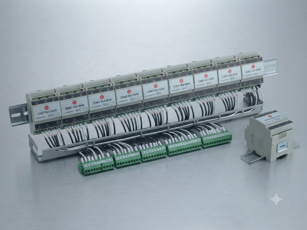
Nex-G Automation Ethernet relay product range reference

Deployment in distributed equipment groups and medium-sized automation panels.

The 8 channel ethernet relay board can be evaluated for distributed equipment groups and medium-sized automation panels. Assign each required electrical circuit to an available relay output and confirm contact ratings, supply voltage and network compatibility before installation.

Channels 8 Channels
Network Ethernet TCP/IP with Client Mode
Switching Up to 250V AC / 30V DC, maximum 10A as specified
Mounting DIN rail or wall-mount options

Applications of the 8 Channel Ethernet Relay

01 Multi-Equipment Automation Panels
02 Building Management and Lighting Control
03 IoT-Based Equipment Switching
04 PLC and SCADA Control Environments
05 Multi-Station Test Equipment
06 Security and Electrical Control Systems

Configuration and integration capabilities

Target IP Configuration Configure the target server address through the available device configuration utility.
Relay Channel Control Operate individual relay channels using the supported ON/OFF control commands.
Network Parameters Configure applicable IP address, subnet mask and gateway settings for the installation.
Connection Monitoring Use configured keep-alive communication to help monitor the network connection.

8 Channel Ethernet Relay Board FAQs

An Ethernet relay board is an electronic switching device that allows connected relay channels to be controlled through a network communication interface. It can be used for remote switching of compatible electrical equipment.
Choose this configuration for distributed equipment groups and medium-sized automation panels when you need eight independently controlled outputs. For a standard six-output solution, see our 6 channel Ethernet relay board.
The relay controller communicates through Ethernet using TCP/IP. The supplied product information specifies Client Mode operation and IP-based control.
Yes. A compatible control application can send supported network commands to operate the relay channels. The connected electrical equipment and control circuit must be designed within the relay contact ratings.
Integration may be possible through a compatible control application or communication interface. The required command format and system compatibility should be confirmed for the specific PLC, SCADA or supervisory system.
The supplied product information lists up to 250V AC or 30V DC and a maximum current rating of 10A. Actual permissible loads depend on the relay model, load type and switching conditions.
The supplied specifications list 12V DC and 24V DC power supply options, depending on the model.
DIN rail and wall-mount form-factor options are listed in the supplied product information. Confirm the mounting arrangement for the selected model.
The supplied specifications list a web-based portal and serial configuration utility. Availability and functions should be confirmed for the specific model.
The supplied technical information lists an operating temperature range of −20°C to +70°C. Confirm the rating for the exact product configuration.